The pipe sections are placed in the middle of the platform and using grippers and rollers raised up to the welding tower.
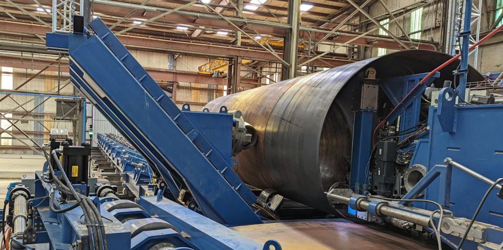
They are to be welded together at the girth joint using submerged arc welding equipment.
There are four pipeline installation methods:
- S-Lay: fast, S-Lay vessel, 10-30 inches diameter, 50-5000 m deep
- J-Lay: slow, J-Lay vessel, 10-30 inches diameter, 50-5000 m deep
- Reel-Lay: very fast, Reel-Lay vessel, up to 12 inches, up to
- Pipeline to
S-Lay
The S-Lay method is used for pipelines with diameters from 10 to 30” in water up to 5000 m. For this type of installation requires an S-Lay vessel, which is basically a floating welding factory, where pieces of 12 m long pipes joint to form the pipeline and lowered to the seabed (Fig. 1). The pipeline from the vessel to the seabed takes an S-shape that why we call the method S-Lay
This type of installation requires an S-Lay vessel, which is basically a floating welding factory, where pieces of 12 m long pipes are continuously joint and lowered to the seabed. The pipeline from the vessel to the seabed takes an S-shape that is why we call the method S-Lay. The layout of an S-lay vessel is shown below.
The main parts are: 1. Pipe transfer crane 2. Pipe storage area 3. the double joint factory 4. the main fire line 5.the tensioners, 6.the stinger
S-Lay is currently used for pipelines with diameter from 10 to 30” in waterdepth up to 2500 m (1000t tension force). With the completion of the vessel Pioneering Spirit (2000t tension force) from Allseas, S-lay will be possible for pipelines with OD of 68”
| Vessel Name | Max Tesion | Diameters | Record Depth [m] | DP |
| Seven Borealis | 600 t | 5″ – 46″ OD | YES | |
| Lorelay | 265 t | 2″ – 28″ OD | 1650 m | YES |
| Global 1200 | 500 t | 4″ – 60″ OD | YES | |
| Castorone | 750 t | 4″ – 60″ OD | YES | |
| Solitaire | 1000 t | 2″ – 60″ OD | 2750 m | YES |
| Pioneering Spirit | 2000 t | 2″ – 68″ OD | YES | |
| Tog Mor | 100 mt | 60″ OD | 100 m | NO |
| Stingray | 140 mt | 6″ – 60″ OD | 100 m |
Advantages:
High pipelaying rate: 2-7 km/day
Wide range of pipeline diameters: 4″ – 60″ OD
Long vessels with large pipe storage capacities
Several production stations (welding, NDT, field joint coating): 6-10 stations
Many experiece contractors and economical aspects
Disadvantages:
Installation depth resticted on vessel tension capacity;
Pipelaying in detail
- Pipe transfer onboard
- Pipe temporal storage
- Bevelling pipe Ends
- Line-up
- Preheating pipe ends
- Welding the bead pass
- Welding the hot pass
- Welding the filler passes
- Welding the cap
- Ultrasonic testing
- Entering the tensioner area
- Grid blasting
- Preheating for applying the field joint coating
- Field joint Coating (FJC)
J-Lay
The J-Lay method is used for pipelines with diameter from 10-50” in deep and ultra deep waters. A vessel with a vertical J-lay tower is required. Pieces of pipe are welded together in the tower and lowered vertically in to the seabed (Fig. 2)
The J-Lay method is used for pipelines with diameter from 10-50” in deep and ultra deep waters. A vessel with a vertical J-lay tower is required. Pieces of pipe are welded together in the tower and lowered vertically in to the seabed (Fig. 2)
| Vessel Name | Tesioner (with clamp) | Diameters OD | Depth [m] | DP |
| Seven Borealis | 940 t | 2″ – 36″ | 3000 m | YES |
| Aegir | 800t (2000 t) | 2″ – 32″ | 3500 m | YES |
| Saipem 7000 | 750t (2000 t) | 4″ – 32″ | YES | |
| Deep Blue | 770 t | 4″ – 28″ | YES | |
| Sapura 3000 | 360 t | 2″ – 20″ | 2750 m | YES |
For example the Pipelaying vessel Aeger can install pipeline up to 32” OD and has a maximum top tension 2,000 mT.
Advandages
- Installation rigid and heavy pipelines in deepwater.
- Installation of fatigue sensitive pipes such as risers.
- Easy installation of PLETs, ILTPs though the moonpool.
- Larger weather window
- Fast and relatively safe abandonment and recovery.
Disadvantages
- Low pipelaying rates due to single welding, NTD, coating station;
- Not suitable for shallow pipelaying.
Reel-Lay
Characteristics
•Fabrication on land “spool base”
•Stalks approximately 1 km long
•Spooled on a reel o/b the vessel
•Lengths depending on reel size and vessel deadweight/stability
•Maximum size 18”
Reeling Process
•Pipe bend through yield on the reel
•During unreeling pipe goes through straightener
•High installation speeds, no welding on board
•Lowered through tensioner in tower
•Sometimes more lengths connected offshore
Pipeline tow
Automatic Ultrasonic Testing (AUT)
Disadvantages of AUT
• More Preparation Time needed for calibrations and to agree
Acceptance Standards
• Each diameter, -wall thickness -and bevel change requires a
specific calibration block
• Crew and equipment more expensive
Radiography
– X ray (tube)
– Gamma Ray (Isotope)
Other NDT methods
– Manual UT
– Magnetic Particle MPI
– Dye Penetrant
Automatic Ultrasonic Testing versus Radiography (“X-ray”)
• Fast: AUT is 1-2 min. ; X-ray at best 4 min, for 2”-3” pipe up to 8 min.
• AUT measures Defect Depth, Height and Length, X-ray only length and type
• AUT good for Planar Defects (more dangerous defect), X-ray for volumetric defects.
Advantages AUT vs. X-ray
• No radiation: Safe
• No film or other expendable items
• Environmentally friendly – no chemical discards
• Digital data storage – no film to store
• Weld Acceptance Criteria can be tuned to Fit for Purpose: less weld repairs
Pipelaying cost
Vessel day rates
Per km cost